Calculate Volume
To access this screen:
-
Solids ribbon >> Operations >> Volume.
-
Using the command line, enter "wireframe-volume"
-
Use the quick key combination "wvo".
-
Display the Find Command screen, locate wireframe-volume and click Run.
Select a closed or open wireframe object, or part of an object, then define parameters and calculate the volume of the data (either the full object or the volume represented by the selected triangles).
The results are reported to a message popup as well as to the Output control bar. You can also export the data automatically to a Datamine file.
Note: This command supports flexible wireframe selection.
You can also use the Wireframe Calculate Volume dialog to calculate the thickness of the selected wireframe in a given direction, and to write useful data attributes back to the original wireframe file or specified external file.
About Thickness calculations
Thickness is the distance inside a wireframe from one side to the other. In some cases this may be measured within a closed wireframe, but in others multiple DTMs may represent the interfaces between different volumes. Note that sense of what is inside a wireframe is determined by the direction of the triangle the point is on. For properly verified objects, this should always underneath true DTMs, and inside of fully closed wireframes.
The Calculate Volume function allows true, vertical and horizontal thickness to be reported. More information on these options can be found in the activity steps below.
To calculate a wireframe's volume and other results:
-
Load a wireframe to be evaluated.
-
Run the command.
-
Decide if you will evaluate an entire wireframe object or only previously selected triangles:
Note: if evaluating selected wireframe data, triangles must be selected before continuing. You can set your wireframe selection mode to triangles using the Project Settings screen. See Project Settings: Wireframing.
-
To evaluate an entire wireframe object, select the Name of the loaded wireframe object to be evaluated. All loaded wireframes are displayed.
-
To evaluate a subset of a loaded wireframe object, ensure the relevant data is selected and pick the Selected triangles option.
-
-
If appropriate, select a Key field.
Where the wireframe contains different zones, data represented by different Key field values will output volume results and other spatial statistics separately for each value. This can be useful for per-level, per-stope or per-region volume reporting, for example.
-
Specify the Object Type being evaluated:
-
Choose Closed volume if the wireframe represents a fully enclosed volume, such as a stope, cavity or cut and fill volume, for example.
-
Choose DTM if the wireframe data is not closed and has no faces overlapping when viewed in plan. If this option is selected, the Volume above DTM and Volume Below DTM options become available (see below).
-
-
Choose your evaluation Options, which depend on the Object Type selected previously:
-
For DTMS, volumes may be reported above the DTM to a reference elevation (Volume above DTM) or below the DTM (Volume below DTM) to a reference elevation (To).
Note: the default value is the highest or the lowest elevation of the DTM depending upon whether the above or below option has been chosen.
-
For any object type, choose the Density value for tonnage calculation. The default is 1.
-
- Choose your Output data options.
-
Calculated volume and other statistics such mass, projected area, true area, spatial extents and minimum and maximum dips is shown in the OutputWindow and displayed in a separate pop-up window. In the event that multiple zones are found (as determined by the Key field column), the results for each zone are reported individually in the Output window, and a combined total is shown in the pop-up window.
Other options are also available for recording both the summary statistics and more detailed calculations:
-
If Output to table is checked, statistics are added to the data object shown in the corresponding list. New names may be entered to create a new table object. Each Key field zone (if specified) is written to a new table row.
Note: the results table format is very similar to that produced by the TRIVOL process.
If this option is unchecked, no results object data is created.
-
-
The results of the calculations may be stored for each triangle in user-defined columns in the original wireframe object, using Write attributes to triangles options. In each case, check the data to write and choose an existing wireframe attribute, or enter a new name to write to a new data attribute.
-
True Area—the area of the surface of the triangle.
-
Horizontal Area—the area if the triangle when projected to a horizontal plane. This may be a positive number for an upwards-facing triangle or negative for a downwards-facing triangle.
-
Azimuth— the azimuth of the plane of the triangle (in degrees).
-
Dip—the dip of the plane of the triangle (in degrees).
You can also write thickness distances to the input wireframe (see "About thickness calculations", above):
-
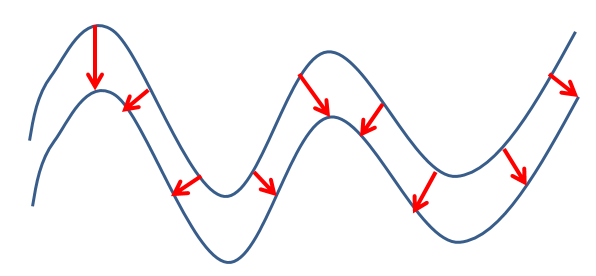
True Thickness—measured perpendicularly to the triangle in 3D space, until it hits another triangle from this wireframe. If no other wireframe is hit in this direction, an absent thickness is recorded.
For horizontal triangles, True Thickness and Vertical Thickness (see below) are identical:
-
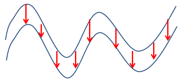
Vertical Thickness—measured directly upwards or downwards (whatever points inside the wireframe), until it hits another triangle from this wireframe. If no other wireframe is hit in this direction, an absent ("-") thickness is recorded:
-
Horizontal Thickness—measured in a direction perpendicular to the triangle, but forced to be horizontal. This distance is measured in this direction until it hits another triangle from this wireframe. If no other wireframe is hit in this direction, an absent thickness is recorded. For vertical triangles, Horizontal Thickness and True Thickness (see above) are identical.
-
Related topics and activities
-
wireframe-volume ("wvo") (command)
-
TRIVOL (process)


